Cut Environments
Cut Environment can be thought of as containers that house the different settings specific to the cut device such as cutmarks, step size, pressure settings, as well as the CutQueue and the Port settings.
You can also find a interesting videos on using cut contour in Ergosoft in our Contour Cut Playlist on Youtube
Add and Manage a new Cut Environment
To manage the different Cut Environments the ErgoSoft RIP features the Cut Environments Manager dialog. The Cut Environments Manager dialog is used to create new Cut Environments, modify existing ones, Import and Export Cut Environments, and delete unused ones.
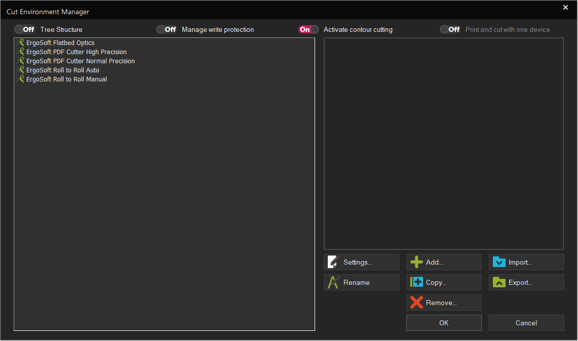
The left hand side of the dialog shows all Cut Environments currently available in this installation of the ErgoSoft RIP. The Cut Environments can be displayed either as a simple list, or in a Tree Structure that groups Cut Environments for the same cutter together. To toggle between the different views, use the Checkbox Tree Structure at the top left of the dialog.
The buttons to the lower right allow you to Rename, Copy, Remove, Import/Export Cut Environments as well as access the settings of individual Cut Environments and add new ones. Most these are pretty self explanatory, so we’ll focus on Add and Settings.
Adding Cut Environments and CutQueues
In order to send data to a Cutter the RIP has to know where to send the data to and where to save the data in the meantime. The Ergosoft CutQueue combines the port settings for the cutter, the spool settings for temporary data and waiting queue for cutjobs into one entity so you can configure and monitor everything together.
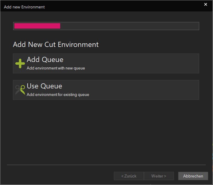
The process of adding a new Cut Environment and CutQueue is exactly the same as it is for Print Environments and PrintQueues, where clicking the Add.. button in Cut Environment Manager launches the configuration wizard that helps you make the necessary configurations.
For a detailed description of the different ways and variants to add Cut Environments and CutQueues, see the article Print Environments > Add Print Environments & PrintQueues.
After going through the configuration, the RIP will automatically bring up your Cut Environment Settings, allowing you to configure the print parameters for your new Cut Environment. If you wish to just cut with default settings at this stage or configure the settings at a later time, you can just confirm with Ok.
Cut Environment Settings
Besides the basic driver architecture, Cut Environments also contain several other settings and aspects that make them a very versatile solution for managing different cutter / Media combinations. These settings can be found in the so called Cut Environment Settings and the settings are used every time something is cut with this Cut Environment.
To access the Cut Environment settings, select a Cut Environment in Tools > Cut Environment Manager. and click the Settings button. Or select one from the Cut Environment drop down menu of the JobComposer toolbar, then click on the Cut Environment Settings button.
The Cut Environment settings are split into different section depending on the type of settings they are about.
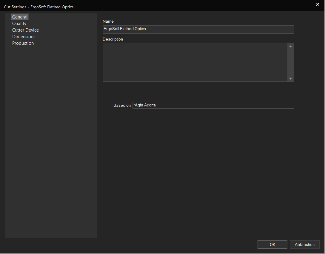
General
This section features the Cut Environment Name, Description and the base driver the Environment is based on. You can enter any name and description you like to help you identify the Cut Environment later.
Quality
Deals with settings related to Cut Quality. By default, Speed and Pressure will use the settings set up on the cut device. Check the box next to the settings to enter custom values and overwrite the machine setting.
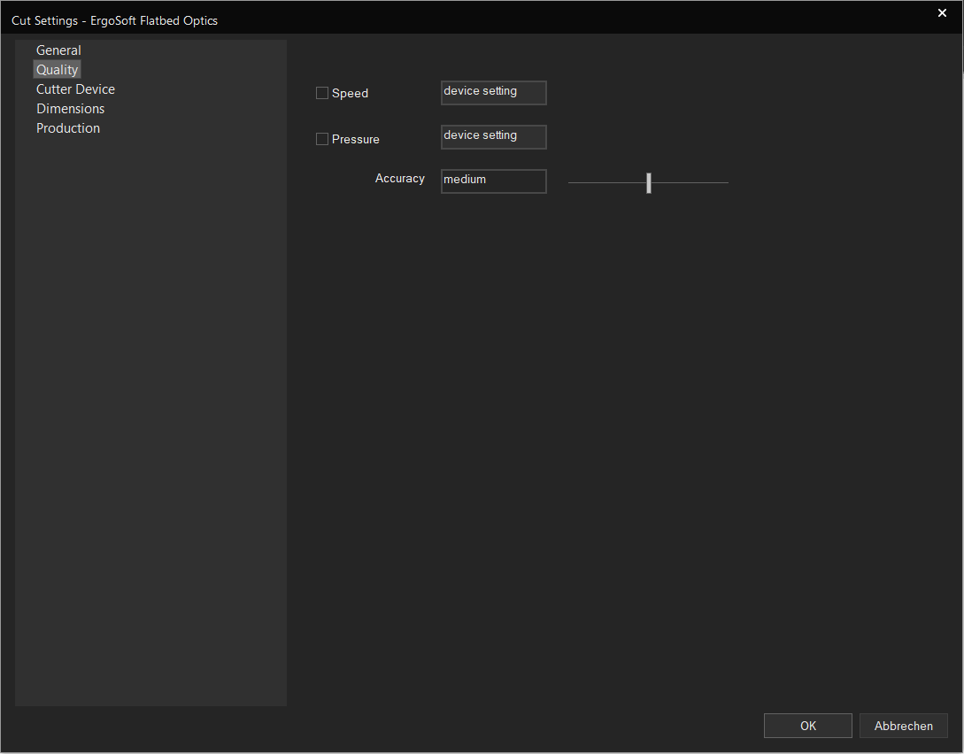
Speed: Set how fast the machine cuts. Increase to make the cutting faster, but decrease if you notice tearing of the material.
Pressure: Sets how much pressure is applied while cutting. The optimal setting varies depending on the material.
Accuracy: Sets how many smaller segments lines get broken into. Higher accuracy means smoother cut lines, but also takes longer to cut.
Cutter Device
Contains the port information to communicate with the cutter as well as the setting for the spool folder.
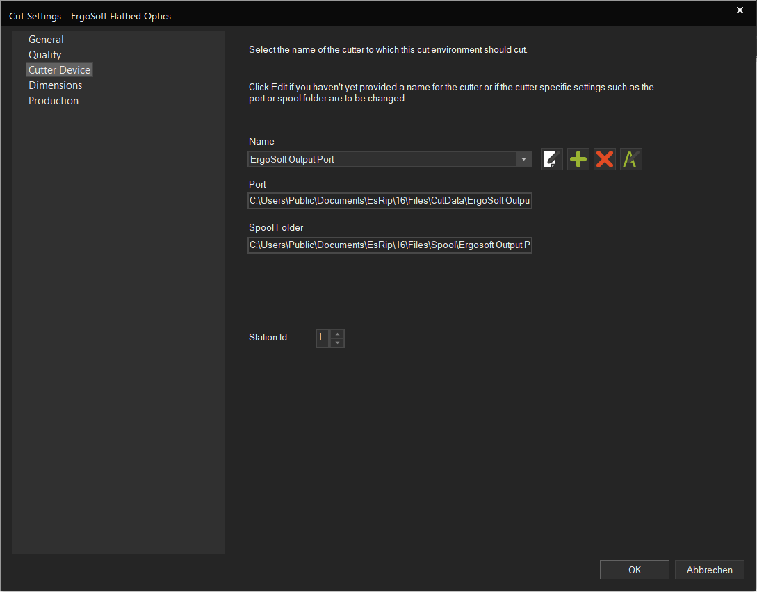
To set up a port, click the Add button next to the dropdown menu and enter the appropriate information for port and spool folder for temporary files. This will automatically create a CutQueue with the port assosciated. Depending on the cutter model you have, different types of port may be available or not.
Dimensions
Settings dealing with the size and dimensions of the cut.
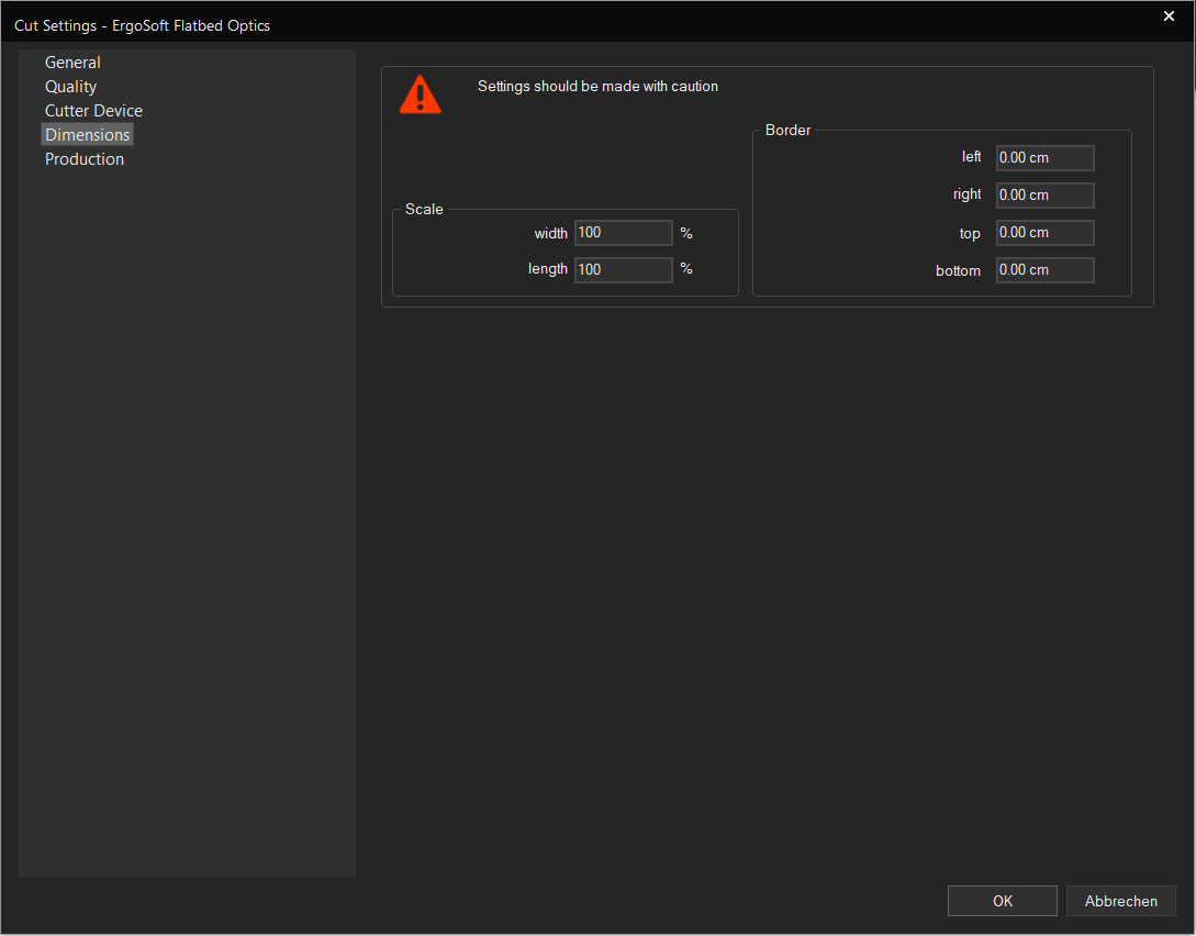
Scale: Lets you set a scaling parameter in width and length to correct size changes in the material or stretching. The cut will be scaled according to the entered value, where 100% is the original cut size.
Border: Lets you set margins for the cut. This will move the cut area according to the entered values, so e.g. enter 2cm left and 2cm top will move the cut 2cm to the right and 2cm down.
Production
Deals with production related options. These may be different depending on the type of cutter you are using.
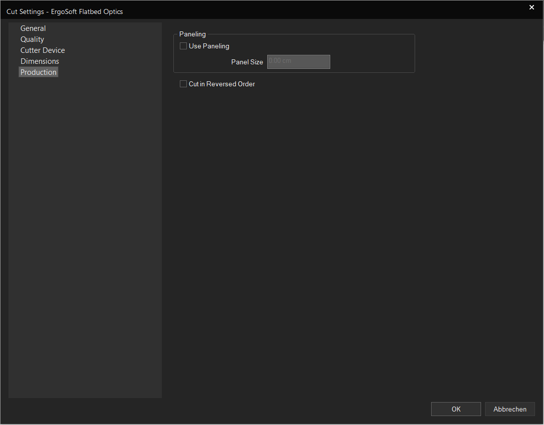
Use Paneling: Paneling means that the printed material is cut in segments, rather than overall. Setting the panel size means that the cutter will first cut the first section, then move on to the next, etc.
Cut in Reversed Order: Begins cutting at what normally would be the end of the cut. This can be helpful depending on how the material is loaded and how the images are printing on the material.
Related Articles
Ergosoft File Output Cut Environments
Ergosoft offers a range of different file output Cut Environments. These drivers output cut files to a designated folder in a format depending on the driver that is used. They are intended for use with Cut Environments that are not technically ...About Print Environments
Introduction Print Environments in Ergosoft RIPs can be thought of as a package of settings relating to a specific printer / material / ink combination. Print Environments are sometimes referred to and thought of as Printer Drivers, but that is only ...Introduction to Contour Cut
In ErgoSoft RIPs, contour cut integrates seamlessly into the production workflow. For Jobs intended to be Cut, the RIP automatically constrains Job space to the width of the cutter to make sure the Job fits. It reserves space around the images and ...Cut
With Delta Automation, it is also possible to automatically prepare a Job for Cut by assigning a Cut Environment to the Job so the appropriate marks are printed and to configure the correct cut path so the Job can automatically go from the Print ...Bleed and Cut Lines
About Bleed and Cut Lines Bleed and Cut Lines are two features intended to be used for images that will be cut out sometime after the printing process, either by machine or by hand. Bleed will add a bleed margin to the image to avoid material color ...