Ergosoft File Output Cut Environments
Ergosoft offers a range of different file output Cut Environments. These drivers output cut files to a designated folder in a format depending on the driver that is used. They are intended for use with Cut Environments that are not technically supported with their own driver in Ergosoft but can receive cut instructions/cut paths in one of these formats.
To add a new Ergosoft file output Cut Environment, go to Cut Environments > Add and select the manufacturer Ergosoft. Then select the type of driver you want to use.
Ergosoft DXF Omnicut Series
Ergosoft DXF outputs DXF files containing the cut paths for cut devices that accept cut files in DXF formats.
The options of the Cut Environment are mostly the same as the ones of other Cut Environments. For more information on the regular Cut Environment settings, see the article Cut Environments.
The main difference is that instead of a regular port you specify a file path as the port to store the generated cut data and that you have file output specific settings in the Device Options of the Cut Settings.
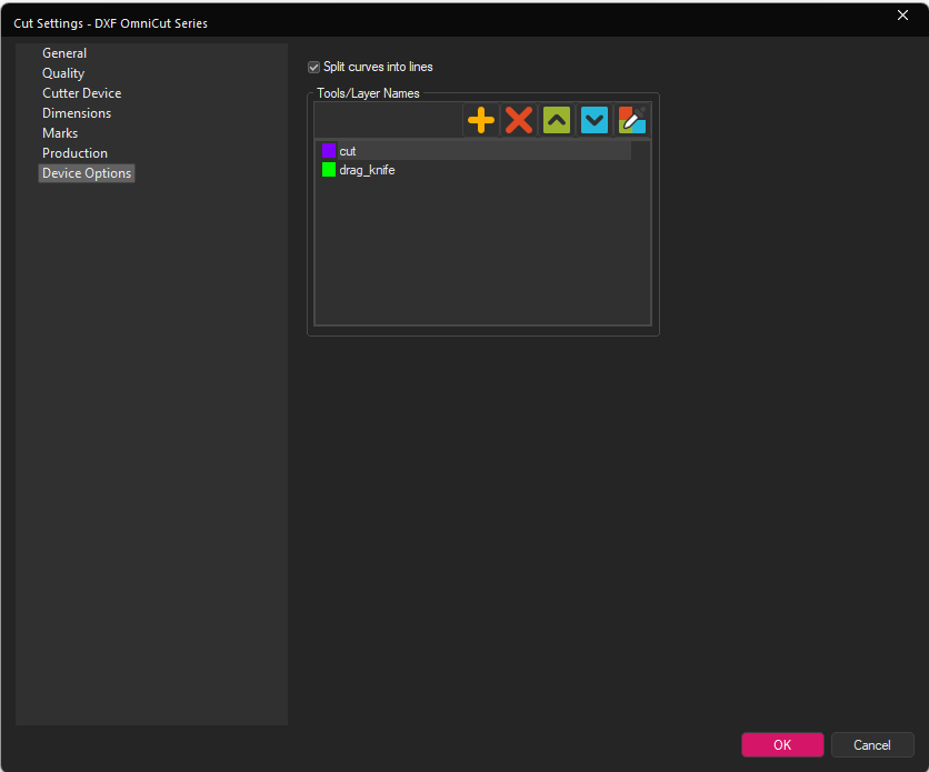
Tools/Layer Names: Lets you specify the tools that the cutting device has and assign them a name and a color so they can be correctly controlled through the output file.
Setting up a tool here and then assign it via Job Cut Settings > Cut Settings > Cutting Tool will create the cut path in the output file with the set color and name.
For the Ergosoft DXF, the dxf file will contain the cut paths in the set color and each on their own layer with the name specified in Tools/Layer Names.
For example, if you want to set up a specific cut path for a drag knife, you can add a Tool/Layer Name with the correct name and color to adress the drag knife on your cutting device, e.g. drag_knife in the Device Options of your Ergosoft DXF Cut Environment.
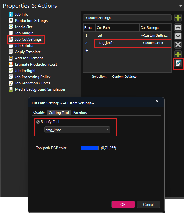
Next go to Properites & Actions > Job Cut Settings and set up a Cut Path. Access the Cut Settings for that Cut Path and go to the Cutting Tool tab. Activate Specify Tool and select the desired tool (e.g. drag_knife). Confirm with Ok.
Now, when you output the Cut file, a .dxf file will be created in your Port folder. The dxf file will contain the cut paths in the set color and each on their own layer with the name specified in Tools/Layer Names to let you adress these tools in the cutter with the machines frontend software.
Ergosoft EPS Omnicut Series
Ergosoft EPS outputs EPS files containing the cut paths for cut devices that accept cut files in EPS formats.
The options of the Cut Environment are mostly the same as the ones of other Cut Environments. For more information on the regular Cut Environment settings, see the article Cut Environments.
The main difference is that instead of a regular port you specify a file path as the port to store the generated cut data and that you have file output specific settings in the Device Options of the Cut Settings.
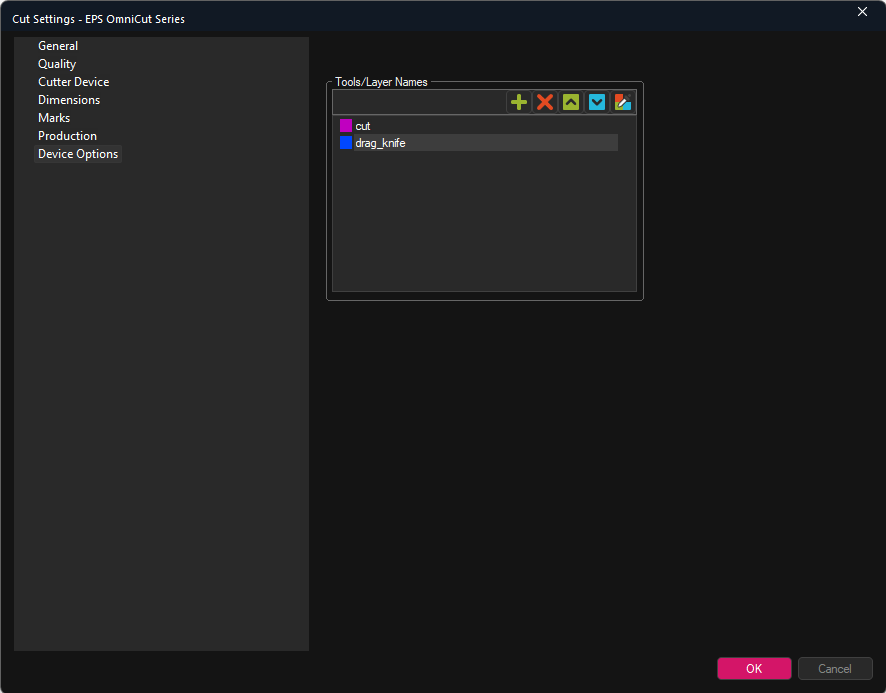
Tools/Layer Names: Lets you specify the tools that the cutting device has and assign them a name and a color so they can be correctly controlled through the output file.
Setting up a tool here and then assign it via Job Cut Settings > Cut Settings > Cutting Tool will create the cut path in the output file with the set color and name.
For the Ergosoft EPS, the EPS file will contain the cut paths as spot colors with the set color and the name specified in Tools/Layer Names.
For example if you want to set up a specific cut path for a drag knife, you can add a Tool/Layer Name with the correct name and color to adress the drag knife on your cutting device, e.g. drag_knife in the Device Options of your Ergosoft EPS Cut Environment.
Next go to Properites & Actions > Job Cut Settings and set up a Cut Path. Access the Cut Settings for that Cut Path and go to the Cutting Tool tab. Activate Specify Tool and select the desired tool (e.g. drag_knife) Confirm with Ok.
Now, when you output the Cut file, a .dxf file will be created in your Port folder. The EPS file will contain the cut paths as spot colors in the set color and the names specified in Tools/Layer Names to let you adress these tools in the cutter with the machines frontend software.
Ergosoft PDF Omnicut Series
Ergosoft PDF outputs PDF files containing the cut paths for cut devices that accept cut files in PDF formats.
The options of the Cut Environment are mostly the same as the ones of other Cut Environments. For more information on the regular Cut Environment settings, see the article Cut Environments.
The main difference is that instead of a regular port you specify a file path as the port to store the generated cut data and that you have file output specific settings in the Device Options of the Cut Settings.
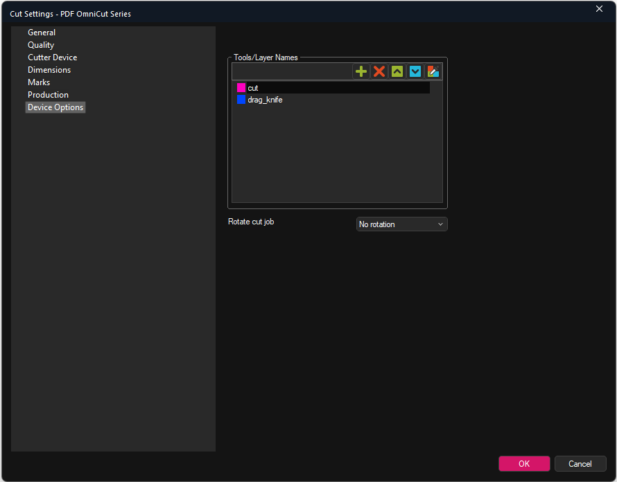
Tools/Layer Names: Lets you specify the tools that the cutting device has and assign them a name and a color so they can be correctly controlled through the output file. Setting up a tool here and then assign it via Job Cut Settings > Cut Settings > Cutting Tool will create the cut path in the output file with the set color and name.
For the Ergosoft PDF, the PDF file will contain the cut paths as spot colors with the set color and the name specified in Tools/Layer Names.
Rotate Cut Job: Lets you specify a rotation for the cut job in the output PDF. The cut paths in the output PDF can be rotated by 90, 180 and 270 degrees to match machine orientation.
For example if you want to set up a specific cut path for a drag knife, you can add a Tool/Layer Name with the correct name and color to adress the drag knife on your cutting device, e.g. drag_knife in the Device Options of your Ergosoft PDF Cut Environment.
Next go to Properites & Actions > Job Cut Settings and set up a Cut Path. Access the Cut Settings for that Cut Path and go to the Cutting Tool tab. Activate Specify Tool and select the desired tool (e.g. drag_knife). Confirm with Ok.
Now, when you output the Cut file, a .dxf file will be created in your Port folder. The PDF file will contain the cut paths as spot colors in the set color and the names specified in Tools/Layer Names to let you adress these tools in the cutter with the machines frontend software.
Related Articles
About Print Environments
Introduction to Print Environments Print Environments in Ergosoft RIPs can be thought of as a package of settings relating to a specific printer / material / ink combination. Print Environments are sometimes referred to and thought of as Printer ...Import Settings from Ergosoft 15 and 16
Updating from an earlier version of a RIP to a more recent one can seem like a daunting task, but with the following steps you can easily take over your printer configurations and settings from Ergosoft RIP 15 to Ergosoft 17. It is recommended to do ...About Ergosoft File Output Drivers
Starting with 17.3, Ergosoft offers a range of different file output Print Environments. These drivers output image files to a designated folder in a format depending on the driver that is used. Composite Contone Print Environments output all color ...Cut Environments
Cut Environment can be thought of as containers that house the different settings specific to the cut device such as cutmarks, step size, pressure settings, as well as the CutQueue and the Port settings. You can also find a interesting videos on ...Cut
With Delta Automation, it is also possible to automatically prepare a Job for Cut by assigning a Cut Environment to the Job so the appropriate marks are printed and to configure the correct cut path so the Job can automatically go from the Print ...